From looking around I'm confident that the UG802 hardware is also sold under a bunch of other name/model combinations, so if you have a similar device with a RK3066 chip in, its likely the same or very similar hardware.
I looked around and couldn't find any decent pictures of the internals of the device, so I decided to take it apart and make a few board scans. Also, the pictures on OvalElephant lead me to believe there were likely a number of test points around the CPU worth investigating -- more on that later.
Disassembling the device is a pain in the butt, as its held together with a number of rather fragile plastic clips. For anyone looking to take theirs apart, the clips extend from the smaller of the two halves. I worked from near the sides of the HDMI port out, using hotel key cards as pry bars and shims. A technique I've proved effective a number of times in the past, worked reasonably well here. However, I required a bit of screw driver prying as the case is quite snug.

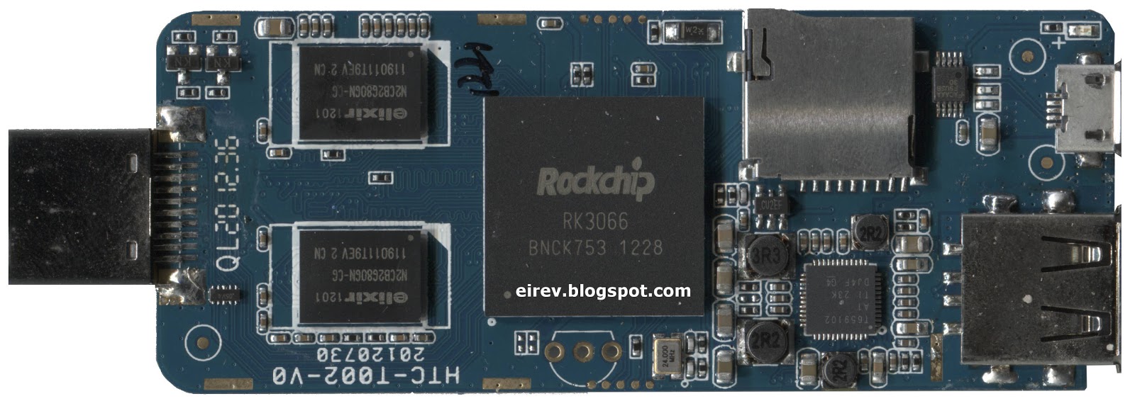
For an inexpensive device I was rather impressed with the finish on the boards. The soldering is clean and and the component placement well done. The only issue I observed was a poor routing on the antenna cable, which caused it to be pinched by the case. Mine was severed, but the insulation and some of the shielding was cut. I suspect if people are having issues with WiFi reception, this is a likely cause.
While I had the device open, I grabbed the oscilloscope and checked out the test pads around the CPU. I was able to locate a serial boot console, which could be useful for development and anti-bricking purposes.

- Green = Ground
- Blue = Serial TxD
- Red = Serial RxD
- White = No signal
- Yellow = 3.3V
- Magenta = 2.5V
I'm guessing the unpopulated TO92 package is intended to be an IR receiver, but that's only a guess.
The use of the other pins is less clear, I'm guessing that by either pulling some set high or low, the device can be placed in a factory flash/recovery mode, however more time with the CPU datasheet and experimentation required to figure this out.
Nice write-up, I look forwards to the results of your research.
ReplyDeleteCould you give a quick explanation of how the average person could fix their wifi reception on these devices? Do we need to solder anything or replace a wire, etc?
ReplyDeleteIf you look at the second board picture, the one with the Realtek chip in the lower right corner, you can see the antenna wire. Its the gray wire. On my unit the antenna itself is a laptop style kapton square at the end of the wire.
DeleteUnfortunately the antenna wire is soldered to the board, so you'd be unsoldering it and soldering another one in its place. You can find suitable replacements on eBay reasonably cheaply.
That said, some of the other UG802 photos I've seen have showed the antenna I have replaced with a "chip" antenna. If thats what your unit has, you're kind of SOL.
Bottom line, before doing anything else, pull the unit apart and see what you've got going on. If you've a wired antenna, like mine, check the wire for cuts and nicks. If it has some, consider replacing it.
Thanks for your reply. I've pulled mine apart and taken a couple of photos:
ReplyDeletehttp://dl.dropbox.com/u/41858/2012-10-03%2015.15.08.jpg
http://dl.dropbox.com/u/41858/2012-10-03%2015.14.13.jpg
Does this look to be in good shape to you?
I've tried using the machine at work with it completely out of its case and I think my wifi speeds have improved (but I am right next to the router, the real test will be when I get home).
Strangely the system reports my signal strength is still only 50% so I wonder if there's a software problem as well as the hardware?
PanicOpticon,
ReplyDeleteI really enjoyed reading the boot log. It was informative. You should come over to the UG802 forums at www.armtvtech.com/armtvtechforum/
Hope to see you there!
3.3V according to pdf should be I2C interface.
ReplyDeletei have an rk3066 tablette and i need to debug it
ReplyDeletei have open it and i found tow pin:
-UART2 TX
-UART2 RX
Is thise tow pin are the same as serial tx and serial RX ?
There is a mistake on your photos.
ReplyDeleteIt must be:
Green = Ground
Blue = Serial RxD2
Red = Serial TxD2
I've compared it with RK3066 datasheet. It looks like the nearest UART pin to the RED label is TX(AB19 ball) from the UART2.
And Blue pin is traced to RX(N22 ball) from UART2.
The oscilloscope test proved my idea: while UG802 is booting the RED labled pin is toggling with 115200 bps baudrate (8.68 us pulse length)
Hi. I have one MK809 bricked (no USB signal - no pin reset etc), only 2 pinguins an R-BOX boot loop.
ReplyDeleteDid you manage to write ROM via UART?