From looking around I'm confident that the UG802 hardware is also sold under a bunch of other name/model combinations, so if you have a similar device with a RK3066 chip in, its likely the same or very similar hardware.
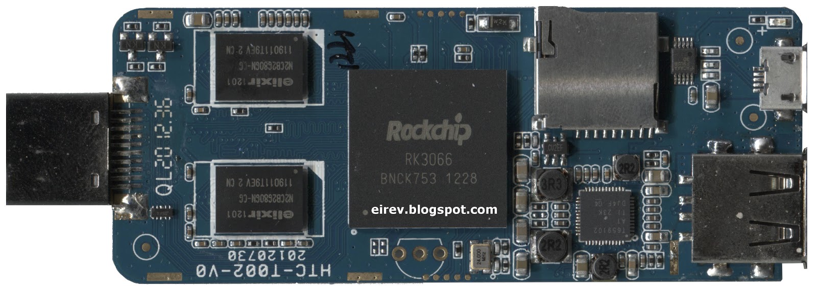
I looked around and couldn't find any decent pictures of the internals of the device, so I decided to take it apart and make a few board scans. Also, the pictures on OvalElephant lead me to believe there were likely a number of test points around the CPU worth investigating -- more on that later.
Disassembling the device is a pain in the butt, as its held together with a number of rather fragile plastic clips. For anyone looking to take theirs apart, the clips extend from the smaller of the two halves. I worked from near the sides of the HDMI port out, using hotel key cards as pry bars and shims. A technique I've proved effective a number of times in the past, worked reasonably well here. However, I required a bit of screw driver prying as the case is quite snug.

For an inexpensive device I was rather impressed with the finish on the boards. The soldering is clean and and the component placement well done. The only issue I observed was a poor routing on the antenna cable, which caused it to be pinched by the case. Mine was severed, but the insulation and some of the shielding was cut. I suspect if people are having issues with WiFi reception, this is a likely cause.
While I had the device open, I grabbed the oscilloscope and checked out the test pads around the CPU. I was able to locate a serial boot console, which could be useful for development and anti-bricking purposes.

- Green = Ground
- Blue = Serial TxD
- Red = Serial RxD
- White = No signal
- Yellow = 3.3V
- Magenta = 2.5V
I'm guessing the unpopulated TO92 package is intended to be an IR receiver, but that's only a guess.
The use of the other pins is less clear, I'm guessing that by either pulling some set high or low, the device can be placed in a factory flash/recovery mode, however more time with the CPU datasheet and experimentation required to figure this out.